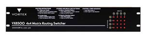
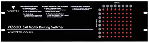
VX8500 4x4, 8x8 - Video / audio routing switcher
Features:
- Low-Cost
- 4x4 and 8x8 versions
- Composite, Y/C, RGB, HD Component, RGBS and RGBHV versions
- Vertical Interval Switching
- Audio/Video or Video only or Audio only versions
- Balanced or Unbalanced Stereo Audio with Breakaway
- Battery Backup
- Flat to Over 200 MHZ
- Store/Recall up to 16 Patterns
- Front Panel and RS232 Serial Control
- Slimline rack enclosures
Applications:
- AV Presentation
- Broadcast
- TV Distribution Systems
- Live Video / Audio Feeds
- Non-Linear Editing Suites
- Medical systems
- Education
- Retail Display switching
- Video Walls
- Home Cinema
- Residential Distribution Systems
- Restaurants / Pubs / Bars / Hotels / Hospitality
- Duplication Systems
The VX-8500 Series is a high performance family of of vertical interval routing switchers for analogue HD/SD Audio/Video applications, housed in ultra-thin rackmount enclosures. Versions are available for Composite video, S-Video, RGB / YUV / HD Component, RGBS and RGBHV with or without balanced or unbalanced stereo audio. A digital version - VX-8500D/8x8 for SDI is also available (see separate information).
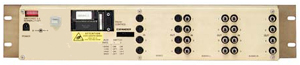
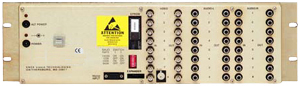
The VX-8500 Series uses high-bandwidth crosspoint ICs that allow any source to be switched to any one or many destinations at the same time without crosstalk. For the analogue versions, video sources may be virtually any 1-volt composite or non-composite video signal: CVBS, Y-C, YUV/RGB or RGBHV. Video and Audio sources can be routed together or independently - they need not have the same destination/outputs. The Balanced Audio switcher uses "active" transformers for input / output which means that it can also switch unbalanced sources and feed to unbalanced destinations with automatic level compensation by shorting the -ve leg to screen. It also avoids the need for external balancing/unbalancing boxes which are prevalent in many mixed systems. Connectors for video are BNC-F except S-Video which uses 4-Pin Mini-DIN/F for inputs / outputs. Unbalanced audio uses RCA Phono connectors whilst Balanced audio uses 2-part Phoenix-type connectors with screw terminals allowing bare-wire connection to the cables.
All units have front-panel control with LED status giving a complete crosspoint "map" with simple source / destination selection. RS-232 serial control is included as standard and allows simple control from automation systems and computers. There is an optional IP interface also available. We have a suite of Windows-based PC software available that provides simple crosspoint selection, scheduling and full control of the switchers.
The crosspoint map is battery backed in case of mains failure and each VX-8500 has user-accessible storage locations that keep complete switcher configurations in non-volatile memory for recall. This means that common configurations can be recalled simply either using the front panel or serial control.
VX-8500 Series switchers are housed in ultra-slim rackmount enclosures - either 2-U (4x4) or 3-U (8x8) with connectors on the rear panel and pushbuttons / status LEDs on the front. They are powered by external universal-input mains power supplies. 2x Video with 2x Audio or 3x Video layers can be accomodated within the same rack enclosure and switchers can be linked for additional switching layers. Because the switchers effectively have no depth, they are often mounted on the rear of rack bays with other equipment mounted from the front of the bay.
Part Number Guide
| Basic Part |
Size |
Video Layers |
Audio Layers |
| VX-8500/ |
4x4/ = 4 inputs x 4 outputs
8x8/ = 8 inputs x 8 outputs
|
V/ = Composite video (BNCs)
YC/ = S-Video (Y + C) (4-Pin Mini-DIN)
RGB/ = RGB (or YUV SD/HD Component) (BNCs)
RGBS/ = RGBS (BNCs)
RGBHV/ = RGBHV / VGA (BNCs)
|
AA = Unbalanced Stereo (phonos)
BB = Balanced Stereo (Phoenix screw terminals)
|
| Specifications |
| Analogue Video: |
| Inputs |
BNC-F 75 Ohm Terminating (Composite, RGB / YUV SD-HD Component / RGBS / RGBHV)
4-Pin Mini-DIN 75 Ohm Terminating (S-Video / YC)
Loop-through / high-impedance inputs available on request
Bridging Tee-pieces available as an option |
| Outputs |
BNC-F 75 Ohm Terminating (Composite, RGB / YUV SD-HD Component / RGBS / RGBHV)
4-Pin Mini-DIN 75 Ohm Terminating (S-Video / YC) |
| Frequency Response |
DC to 200 MHz / -3dB @ 150 MHz @ 300mv; Typ -6dB @ 200 MHz / -3dB @ 115 MHz @ 1.0v |
| Crosstalk |
Typ < -70dB @ 5 MHz all I/Ps hostile
Typ < -55dB @ 20 MHz all I/Ps hostile
Typ < -25dB @ 100 MHz all I/Ps hostile
Typ < -40dB @ 200MHz one I/P hostile |
|
| Balanced Audio: |
| Inputs |
2-part 3-way "Phoenix-type" connectors with screw terminals for +/-/Scn (bare wire), 10K High Impedance or 600R |
| Outputs |
2-part 3-way "WECO-type" connectors with screw terminals for +/-/Scn (bare wire), typically 100R or 600R Balanced |
| Frequency Response |
20Hz to 30KHz ±0.25dB |
| Input Level |
0, +4 or +16 - clipping at +18dBu |
| Output Level |
Same as input level (unity gain ±0.2dB) |
| Crosstalk |
<-90dB @ 20KHz |
| Hum and Noise |
<-90dB |
|
| Unbalanced Audio: |
| Inputs |
RCA Phono, 100K High Impedance, DC Coupled |
| Outputs |
RCA Phono, typically 1K |
| Input Level |
Up to 2V pk-pk |
| Output Level |
Same as input level (unity gain ±0.2dB) |
| Frequency Response |
20Hz to 20KHz ±0.25dB |
| Crosstalk |
<-80dB at 20 KHz |
| Hum and Noise |
<-80dB |
|
| Control: |
| Serial |
RS-232 on D-9M (standard) |
| IP |
Optional RJ45 10-BaseT Ethernet Inteface |
| Front Panel |
Either Simple panel (no Audio Volume/Tone adjust)
or Enhanced - provides Audio adjustment
or None - Blanking Panel available for secure applications |
| Software |
VX-85/Connect for crosspoint control (option)
SchedulePak-II for scheduled recall of stored patterns (option)
VirtualCP Virtual Control panel - provides control of individual crosspoints (option) |
| Serial Commands |
Switch (A,V,B) - selects the Source/Input to be routed to a Destination/Output
Queue (E,F,G) - sends series of commands but waits until final command before executing
Salvo (X,Y,Z) - switches a number of outputs to the same input
Store (S) - stores Switcher Crosspoint Patterns for recall (same number as number of O/Ps)
Recall (R) - recalls stored pattern
Protect (P) - protects an output from being changed
Un-protect (U) - unprotects and output |
| Control Panels |
SER-PB - 16 + 4 Intelligent Push Button Panel for one output, stored Salvos or X-Y configurable
SER-IR - Infra-Red for one output, stored Salvos or X-Y configurable
SER-PB-IR - 16 + 4 Intelligent Push Button Panel for one output, stored Salvos or X-Y configurable - plus Infra-Red
SER-KBD - Desktop Keypad for control of complete matrix
SER-KBD-RCK - 3-U Rack-mounted Keypad for control of complete matrix |
| Other Control Interfaces |
NET-CNTL - desktop hardware interface to convert IP to/from serial for connection to VX-8*** series switchers
USB-CNTL - desktop hardware interface allows PC communications programs to control VX-8*** series switchers via USB
MLT-CNTL - Multi-Layer Translator - Hardware interface with one RS-232 input / 4x RS-232 outputs to allow combinations of up to 4 VX-8*** switchers for up to 8-layers Video/Audio with up to 999 outputs |
|
| Power Requirements: |
| Consumption |
30VA typically 15V DC @ 1.5A from plug-in switch-mode module (supplied) |
| External PSU |
100-240VAC 50-60Hz with IEC mains input, 30VA |
| Connector |
5mm / 2mm Coaxial - +ve inner |
|
| Physical: |
| Operating Temperature |
0-50°C (32-122°F) |
| Relative Humidity |
0% - 90% non-condensing |
| Size |
4x4 = 2-U x 19" Rackmount - 483 x 89 x 50mm deep (19" x 3.75" x 2") approx
8x8 = 3-U x 19" Rackmount - 483 x 133 x 50mm deep (19" x 5.25" x 2") approx
8x16 = 6-U x 19" Rackmount - 483 x 266 x 50mm deep (19" x 7.5" x 2") approx
16x8 = 6-U x 19" Rackmount - 483 x 266 x 50mm deep (19" x 7.5" x 2") approx
16x16 = 6-U x 19" Rackmount - 483 x 266 x 50mm deep (19" x 7.5" x 2") approx
V--, V+AA, V+BB, YC--, YC+AA, YC+BB, RGB-- = 1 frame
RGB+AA, RGB+BB, YUV--, YUV+AA, YUV+BB, RGBS-- RGBS+AA, RGBS+BB, RGBHV--, RGBHV+AA, RGBHV+BB = 2 frames - only one has Front Panel Control |
| Weight |
2-U = 3Kg (6lbs) approx
3-U = 4Kg (8lbs) approx
6-U = 7Kg (14lbs) approx |
|